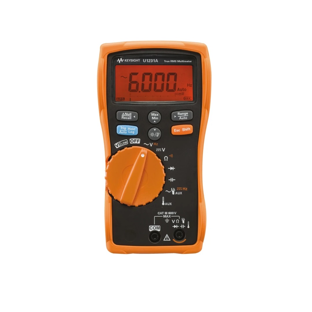
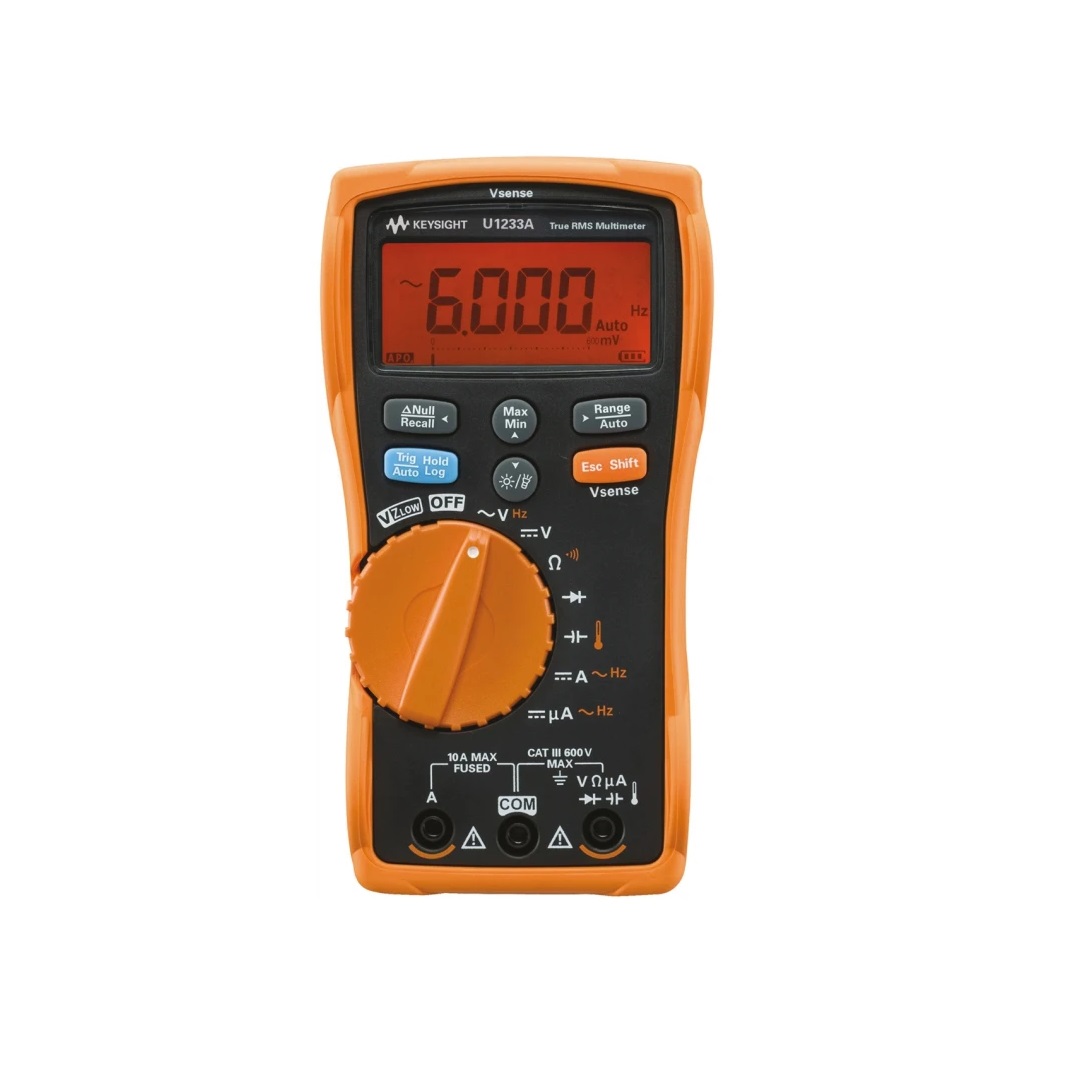
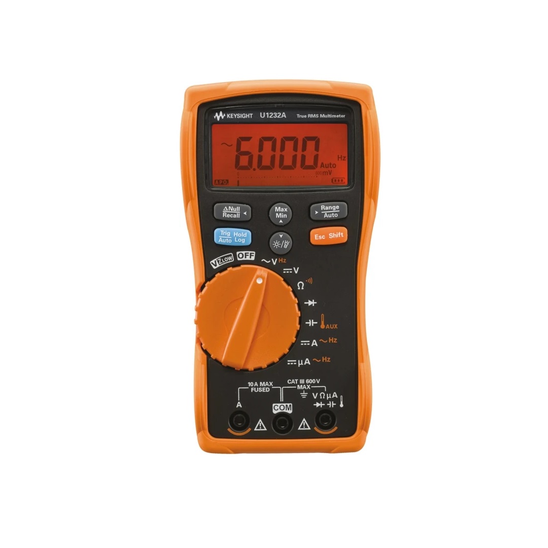
info@irct.co.th
"Accelerating innovation to connect and secure the world"
"มืออาชีพ ได้มาตรฐาน ทันเวลา พัฒนาต่อเนื่อง สร้างความพึงพอใจให้ลูกค้า"
COURSE OUTLINE:
An oscilloscope is a laboratory instrument commonly used to display and analyze the waveform of electronic signals. Scope draws a graph of the instantaneous signal voltage as a function of time. This course will teach the various aspects of Oscilloscope key parameter like BW, Sampling rate, deep memory, trigger and measurement techniques.
COURSE LENGTH: 1/2 Day
Instrument: DSO1000 or DSO2000X series or equivalent
Document: Training manual & Certification
Audience Type: Engineers and technicians who are using Digital Oscilloscope.
Detailed Course Agenda:
1 Time Domain vs. Frequency Domain
2 Block Diagrams
3. Waveform Acquisition Definitions
4 Sampling Techniques
5 Aliasing & Under-Sampling
6 Memory
7 Triggering
8 Display Modes
9 Mixed Signal Oscilloscope : Analog vs. Digital
10 Probes
11 Trigger technique
12 Test & Review
LAB & Workshop
LAB 1: DSO Measurement function
LAB 2: Measurement function
LAB 3: Trigger function
COURSE OUTLINE:
An oscilloscope is a laboratory instrument commonly used to display and analyze
the waveform of electronic signals. Scope draws a graph of the instantaneous signal
voltage as a function of time. This course will teach the various aspects of Oscilloscope key
parameter like BW, Sampling rate, deep memory, trigger and measurement techniques.
Advance measurement function: Segment memory, Zone Trigger, Serial data decoder.
COURSE LENGTH: 1 Day
Instrument: DSO3000 or DSO4000X series or equivalent
Document Training manual & Certification
Audience Type: Engineers and technicians who are using Digital Oscilloscope.
Detailed Course Agenda:
1 Time Domain vs. Frequency Domain
2 Block Diagrams
3. Waveform Acquisition Definitions
4 Sampling Techniques
5 Aliasing & Under-Sampling & Memory
6 Build-in Arbitrary Generators & Training signal
7 Advance triggering
8 Display & update rate
9 Mixed Signal Oscilloscope : Analog vs. Digital
10 Probes : Passive & Active probe
11 Trigger technique
12 Serial decoder info
13 Test & Review
LAB & Workshop
LAB 1: DSO Measurement function
LAB 2: FFT Measurement & math function
LAB 3: Zone Trigger
LAB 4: Build-in Arbitrary Generators
LAB 5: Segmented memory & Mask Test
LAB 6: Serial decoder I2C(Inter-IC bus),SPI
LAB 7: Serial decoder CAN, LIN
COURSE OUTLINE:
A data acquisition system (DAQ) is an information system that collects and stores
information. It is used in industrial and commercial electronics, and scientific equipment to
capture electrical signals or environmental conditions on a computer device. A data
acquisition system is also known as a data logger. This course will teach the various
aspects of temperature transducer, data logger module. BenchLink data logger program
used for controlling and storing data.
COURSE LENGTH: 1/2 Day
Instrument: 37970A, 37972, DAQ970A or equivalent
Document: Training manual & Certification
Audience Type: Technicians or operator who are using Data logger.
Detailed Course Agenda:
1 Data Logger System - Transducers
2 Data Logger System Architecture & Block Diagrams
3 Data Logger Module
4 Common modern temperature sensors: Thermocouples, Thermistor, RTD
5 Signal Conditioning
6 Multiplexing
7 Integrating A/D Converter
8 Data Logger System - Wiring Errors
9 Summary - System Accuracy
10 Software BenchLink data logger
11 Test & Review
LAB & Workshop
LAB 1: Voltage, Current, Ohm Measurement
LAB 2: Using software BenchLink data logger to measure Temperature scan
LAB 3: Math and Offset function
COURSE OUTLINE:
An LCR meter is a type of electronic test equipment used to measure the inductance
(L), capacitance (C), and resistance (R) of an electronic component. In the simpler versions
of this instrument the impedance was measured internally and converted for display to the
corresponding capacitance or inductance value.
This course will teach the various aspects of true inductance or capacitance, as well as the
equivalent series resistance of capacitors and the Q factor of inductive components
COURSE LENGTH: 1/2 Day
Instrument: E4980AL LCR meter or equivalent
Document Training manual & Certification
Audience Type: Technicians or operator who are using LCR meter.
Detailed Course Agenda:
1. Introduction Impedance Basics : L C R
2. Impedance Plane : Quality and Dissipation Factors
3. Series and Parallel Models
4. Equivalent circuit models of Capacitor, Inductor
5. Impedance measuring Method : Auto Balanced, I-V, RF I-V Method
6. 4 Terminal Configuration
7. Test Fixtures selection
8. Errors and Compensation : Short, Open, Load
9. Test & Review
LAB & Workshop
LAB1: Measurement model
LAB2: Capacitance measurement.
LAB3: Using Frequency scan function to measure Resonance circuit.
COURSE OUTLINE:
The spectrum analyzer is a widely used analytical instrument, mainly for detecting RF and
microwave signals, and has certain applications in many fields. These devices display the
individual elements of these signals. The frequency appears on the horizontal axis, and the
amplitude is displayed on the vertical axis. There are some parameters in the spectrum
analyzer that need to be noticed by the user.
COURSE LENGTH: 1 Day
Instrument: Keysight Spectrum N90XX series or equivalent
Document Training manual & Certification
Audience Type: Engineers and technicians who are using spectrum analyzers.
Detailed Course Agenda:
1. Vector Spectrum Analyzer: Basic info & measure
2. Time Domain VS Frequency Domain
3. Basic & Key parameter
a. Frequency parameter: Start, Stop, Span, RBW, VBW
b. Amplitude parameter: Reflevel, Attenuation, Detector
c. Trace & Display function :Maxhold ,Minhold, View ,Blank,Trace
d. Marker & Marker function : Peak Search, Marker fuction
4. Amplitude unit & Correction
5. Dynamic Range
6. RF Test (Tx & Rx) parameter
a. Occupied Bandwidth
b. Channel Power
c. ACP
d. Harmonic Distortion
e. Burst Power
f. Spurious Emissions
7. Basic operation
8. Digital Radio Design and Troubleshooting
9. Test & Review
LAB & Workshop
LAB 1: Measuring Multiple Signals (Real signal measurement)
LAB 2: Measuring a Low Level Signal & Improving frequency resolution
LAB 3: Measure: Occupied Bandwidth, Channel Power, Adjacent Channel Power.
LAB 4: Measuring the Signal-to-Noise
COURSE OUTLINE:
A vector signal analyzer is an instrument that measures the magnitude and phase of the
input signal at a single frequency within the IF bandwidth of the instrument. The primary
use is to make in-channel measurements, such as error vector magnitude, code domain
power, and spectral flatness, on known signals.
COURSE LENGTH: 1 Day
Instrument: VSA86900A or equivalent
Document Training manual & Certification
Audience Type: This topic is suitable for engineers working or interested in digital
communication.
Detailed Course Agenda:
1 Frequency Domain Measurements
a. Frequency
b. Channel Power / Band power
c. Relative Frequency and Amplitude
2 VSA Measurement Platform
3 Keysight 89600 Vector Signal Analysis
4 Digital Demodulator Theory of Operation
5 Digital modulation Format: BPSK, QPSK, QAM ,PSK,…
6 Demodulation Parameter
a. Symbol rate
b. Points / Symbol
c. shaping filters
d. Format
e. Trace Data
7 Analysis parameter
a. EVM
b. I/Q gain Imbalance
c. Quadrature Error
d. Filtering Errors
e. Symbol Rate Errors
f. Spirus and Interfering Signals
8 Test & Review
LAB & Workshop
LAB 1: Function of 89600 Vector Signal Analyzer
LAB 2: Managing trace windows, windows tool
LAB 3: Tutorial Recorded Signals
LAB 4: Digital signal1 Analysis
LAB 5: Digital signal2 Analysis
LAB 6: Digital signal3 Analysis
COURSE OUTLINE:
RF Network analyzers are used to measure components devices (amplifiers, filters,
cable, antenna…), and sub-assemblies circuits. Network analyzers commonly measure s–
parameters because reflection and transmission of electrical networks are easy to measure
at high frequencies, they can be used to measure S-parameters like S21: Magnitude,
Phase, S11: VSWR, Return loss.
COURSE LENGTH: 1 Day
Instrument: Keysight VNA ENA Series E5063A, E5071C or equivalent
Document Training manual & Certification
Audience Type: Engineers and technicians who are using Network analyzers.
Detailed Course Agenda:
1. Vector Network Analyzer: Basic RF info & RF Device measurement
a. Transmission Line Basics (Low vs. High Frequency Behavior)
b. High-Frequency Device Characterization
2. RF network parameter
a. Reflection parameters & definition:
b. Return loss, VSWR, Smith Chart, Impedance.
3. Transmission parameters & definition:
a. Insertion loss, Gain, Phase, Group Delay, Real, Imaginary
4. S-Parameter : S11 S21,S12 ,S22
5. Display Format : Log Mag, Phase ,SWR, Delay, Polar, Amplitude unit & Correction
6. Calibration Type & technique:
a. Response Calibration
b. One port Calibration
c. Full Two port Calibration
d. Electronic Calibration
7. Characteristic of RF Device and measurement
a. Filter (LP, HP, BPF): BW, Q, Center Frequency, Rejection
b. Antenna GSM, WLAN: VSWR, Impedance, Return loss
c. Coaxial Cable: Cable loss, Cut off Frequency
8. Test & Review
LAB & Workshop
LAB1: Filter measurement with calibration
LAB2: Cable measurement
LAB3: Antenna test
COURSE OUTLINE:
Cable & Antenna test (Sweep tester) is a simple kind of Vector Network Analyzer focusing
on measuring VSWR, return loss, distance-to-fault and cable loss.
Measurements mode for cable & antenna tester: Insertion loss (2-port, 1port) , Return loss
or VSWR, Distance-to-fault (DTF)
COURSE LENGTH: 1 Day
Instrument: FieldFox or equivalent
Document Training manual & Certification
Audience Type: Technicians or engineers working on transmission lines, antenna and
for antenna installation for mobile systems.
Detailed Course Agenda:
1. RF Background
a. Transmission-line basics
2. High-Frequency Device Characterization
a. Reflection parameters
b. Transmission parameters
3. Cable & Antenna tester
4. Computer control Program
a. Remote control
b. Test report
5. Cable & connector
a. Characteristic
b. Test parameter :Impedance, loss/Attenuation, Velocity factor, Cuttoff
Frequency
c. Error & Calibration
d. measurement technique
i. Cable loss (1-port)
ii. Cable loss (2-port)
iii. Distance to fault
6. Antenna
a. Type & Characteristic
b. Parameter: Return loss, SWR, Impedance ,Pattern
c. Error & Calibration
d. Principles of testing and precautions
7. Conclusions and Summary
8. Test & Review
LAB & Workshop
LAB 1: Computer control Program
LAB 2: Inspection of quality of transmission lines
LAB 3: Antenna measurement and testing
LAB 4: Verify communication Antenna system
Sign up to our email